For applications it is often desirable to realize phase conjugation with high reflectivity. Using FWM, the problem is that the reading pump wave is erasing the grating inside the crystal at the same time as it reads it and therefore the reflectivity can not be unlimited increased by increasing the intensity of the read wave.
Here, an arrangement (Fig.1) is studied where first the grating
is written by signal (S) and pump wave (P) and only then the read
wave (L) is switched on by a shutter. The intensities and intensity
ratios can be varied. Unexpanded laser beams are used.

Figure 1: Experimental arrangement. Intensities:
S, P,
L
So, it should be possible to reach reflectivities higher than in the steady state at least for a short time. Fig.2 shows the course in time of the reflectivity after switching on the read wave.
The reflectivity starts at a certain value R(t=0) and then it decreases till it reaches the steady state value R(t®¥).
At t=0, the read wave is diffracted at an existing grating. Then the grating is erased by the read wave, that means that the depth of the diffractive index distribution is decreased. The steady state is reached because writing and erasing of the grating proceed simultaneously.
In Fig.2 the ratio P/S and therefore the modulation of the intensity
distribution is constant for all curves. The sum intensity S+P
is the parameter varied between the curves. In Fig.3 only the
signal intensity S is the varied parameter, whereas P and L are
constant.

Figure 2: Reflectivity when the read wave L is switched on.
P and S
are variable with a constant ratio.
Both figures, Fig.2 and Fig.3, show qualitatively the same courses
in time. The graphs good correspond with our assumption.

Figure 3: Reflectivity when the read wave L is switched on.
S is variable.
The switched reflectivity as well as the steady state reflectivity in dependence on the ratio L/(S+P), read wave intensity over the intensities of the writing beams, are shown in Fig.4.
The course of the graph for R(0) can be explained as follows:
The read wave L is diffracted at an existing and uninfluenced
grating. Therefore, R increases with increasing L. The deviation
for very small S+P can be attributed to thermal relaxation.

Figure 4: Switched and steady state reflectivity.
The graph R(¥) can be explained as follows:
The interference of S and P builds the intensity distribution

The influence of the additional read wave L reduces the value
of the visibility from m to k, where

The diffraction efficiency h at a thick
grating is given by

This yields

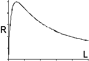
The course of the function R=f(L) is shown in the following picture.

An qualitative correspondence to the first part of the curve for
R(¥) in Fig.4 is obvious.
The increase in the second part of this curve can be explained by TWM between the initially created pc-wave (Win) and the read wave L. The TWM gain for Win is as higher as smaller Win is with respect to L. The pc-wave is stronger amplified and therefore R(¥) is higher for smaller S+P or higher L.
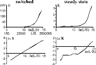
Results of reflectivity measurements where only the intensity of the signal wave S is varied but L and P are kept constant are shown in Fig.5.
It is important to note that in the switched regime a real amplified reflection (R>1, R=output/input) is possible (for small S up to 150), whereas the steady state reflectivity is much lower (maximum: R»3).
In both cases the reflectivity increases with decreasing signal intensity S. The limit for the measurements is given by the sensitivity of the sensor (L/S®106).
In the steady state real amplification is possible but only for
very small signal intensities S.

Figure 5: Switched and steady state reflectivity.
The signal intensity S is varied.
In conclusion, the switched regime enables to reach high reflectivity
with a four-wave-mixing arrangement, but just for a short time.
It could be used for applications where only the intensity just
in a moment is important.
Acknowledgment
This research has been partially supported by the
Deutsche Forschungsgemeinschaft (DFG) within the Innovationskolleg
"Optische Informationstechnik" (INK 1/A1) at the Friedrich-Schiller-Universität
Jena.